Investment Casting Fundamentals
Investment casting, also known as the lost-wax process, is a precision metal-forming technique that produces complex, high-integrity components. The name derives from the use of a disposable pattern—typically wax—that is “invested” or surrounded by refractory ceramic material to create a mold.
The process follows these fundamental steps:
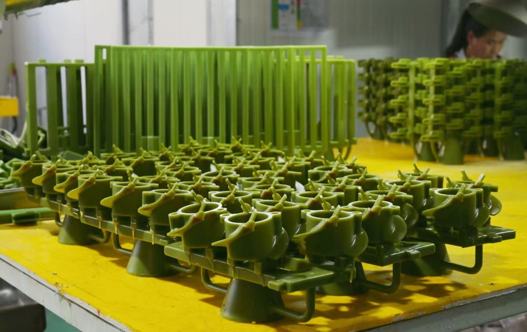
First, a wax replica of the desired component is created through injection molding. Next, the wax pattern receives multiple coatings of ceramic slurry to build a robust shell. Once hardened, the wax is melted and drained away, leaving a hollow cavity. Subsequently, molten metal pours into this cavity and solidifies. Finally, the ceramic shell breaks away to reveal a near-net shape casting requiring minimal secondary work.
Why it matters: Investment casting proves indispensable across aerospace, medical, energy, and automotive sectors because it delivers exceptional surface finish and dimensional accuracy while accommodating an extraordinary range of materials.
Understanding the Silica Sol Advantage
Within the investment casting family, the silica sol process represents the pinnacle of precision and performance. The distinction lies in the binder system—the material that holds the ceramic particles together—used to construct the ceramic shell.
What Makes Silica Sol Different?
Unlike traditional binders such as water glass or conventional ceramic mixes, silica sol employs colloidal silica—a stable suspension of microscopic silica particles in water. Consequently, this choice transforms the casting outcome:
| Characteristic | Silica Sol Advantage |
|---|---|
| Shell Density | Superior strength that withstands extreme temperatures without deformation |
| Chemical Stability | Remains inert even with reactive metals, preserving surface integrity |
| Surface Quality | Exceptionally smooth shell interior imparts superior finish to castings |
| Process Control | Controlled drying and building yields consistent, repeatable results |
Step-by-Step: The Silica Sol Workflow
Pattern Assembly: High-quality wax patterns are first injected and carefully assembled onto a central sprue, forming what industry professionals call a “tree.”
Shell Building: During this stage, the tree undergoes repeated dipping in silica sol slurry, followed by applications of fine zircon or alumino-silicate sand. Importantly, each layer dries under rigorously controlled temperature and humidity to ensure optimal bonding.
Wax Removal: Once the shell reaches sufficient thickness, high-pressure steam in an autoclave melts the wax out rapidly and completely. As a result, this leaves a pristine, crack-free ceramic cavity.
Pouring and Finishing: After firing to sinter the ceramic, the shell receives molten metal—often poured pre-heated to ensure even thin sections fill completely. Cooling, shell removal, and finishing then reveal components ready for demanding applications.
Key Benefits of Silica Sol Casting
The advantages of choosing silica sol become clear when examining measurable outcomes.
Exceptional Surface Finish
Typical roughness values reach Ra 1.6 to 3.2 micrometers—roughly equivalent to a fine polished surface. This level of smoothness often eliminates secondary polishing or machining. By contrast, this contrasts sharply with the rougher surfaces of sand casting or traditional water-glass investment casting.
Superior Dimensional Accuracy
Silica sol casting routinely holds tolerances of ±0.05 to ±0.15 millimeters, meeting or exceeding ISO CT4 to CT6 standards. Consequently, critical features arrive at or near final dimensions, reducing machining burden and preserving metallurgical integrity.
Design Flexibility
The process readily produces complex geometries that challenge other methods:
Internal cavities and undercuts
Thin walls down to 0.5 millimeters—about the thickness of a credit card
Features that would challenge forging operations
Consolidation of multiple components into single castings
Material Versatility
This capability best distinguishes silica sol from other precision casting methods:
| Material Category | Common Examples |
|---|---|
| Stainless Steels | 304, 316, 17-4PH, duplex grades |
| Carbon Steels | Low alloy, medium carbon |
| Copper Alloys | Bronze, brass, aluminum bronze |
| Nickel-Based Superalloys | Inconel, Hastelloy, Monel |
| Cobalt-Based Alloys | For medical and high-temperature applications |
Material Efficiency
Because castings emerge near their final shape, material waste typically ranges from five to fifteen percent. For perspective, this stands in stark contrast to the seventy percent or more waste common when machining complex parts from solid bar stock. Moreover, this translates directly to cost savings, particularly with expensive high-performance alloys.
Mechanical Integrity
The hot mold characteristic promotes directional solidification and reduces porosity. As a result, this yields dense castings that respond predictably to heat treatment and exhibit mechanical behavior consistent with wrought materials.
Comparative Analysis: Silica Sol vs. Alternative Methods
Understanding where silica sol fits within the broader manufacturing landscape helps engineers and buyers make informed decisions. The following comparisons highlight key differences.
Silica Sol vs. Water Glass Investment Casting
| Factor | Silica Sol | Water Glass |
|---|---|---|
| Surface Finish | Ra 1.6–3.2 µm | Ra 6.3–12.5 µm |
| Shell Integrity | Superior, crack-resistant | Prone to defects |
| Typical Applications | Aerospace, medical, high-end industrial | General engineering |
| Cost Position | Premium | Economy |
Water glass shells cost less, but they cannot match the quality required for mission-critical components.
Silica Sol vs. Sand Casting
| Factor | Silica Sol | Sand Casting |
|---|---|---|
| Typical Part Size | Grams to 30kg | Kilograms to tons |
| Tolerances | ±0.05–0.15mm | Millimeters |
| Surface Finish | Excellent as-cast | Requires extensive machining |
| Complexity | High (internal cavities) | Low to moderate |
Sand casting suits large, simple parts where precision matters less. In contrast, silica sol delivers components often ready for immediate use.
Silica Sol vs. Die Casting
| Factor | Silica Sol | Die Casting |
|---|---|---|
| Material Range | All castable alloys including superalloys | Primarily aluminum, zinc, magnesium |
| Part Integrity | Fully dense, heat-treatable | Porosity prevents heat treatment/welding |
| Economic Volume | 50–5,000 pieces | 10,000+ pieces |
| Tooling Cost | Moderate | High |
For high-volume aluminum components, die casting offers speed. However, for steel, superalloys, or parts requiring heat treatment, silica sol is the only choice among precision casting methods.
Silica Sol vs. Precision Forging
| Factor | Silica Sol | Precision Forging |
|---|---|---|
| Geometric Complexity | High (complex 3D shapes) | Low to moderate |
| Mechanical Properties | Excellent (heat-treatable) | Superior (grain flow) |
| Tooling Cost | Moderate | High |
| Part Consolidation | Multiple features in one casting | Often requires assembly |
Forging delivers exceptional strength through grain flow. Nevertheless, silica sol produces shapes that would require multiple forged components welded together.
Silica Sol vs. CNC Machining
| Factor | Silica Sol | CNC Machining |
|---|---|---|
| Material Waste | 5–15% | Up to 80% |
| Complex 3D Shapes | Cast directly | Time-consuming, expensive |
| Lead Time | Moderate for tooling | Fast for simple parts |
| Cost Efficiency | High for complex geometries | High for simple geometries |
Machining a three-dimensional contoured part from solid stock consumes enormous time and material. By comparison, silica sol produces that same geometry near-net, requiring machining only on critical mating surfaces.
Industry Applications
The capabilities of silica sol casting find expression across industries where performance requirements leave no room for compromise.
Aerospace and Defense
Turbine blades and nozzle guide vanes in superalloys like Inconel and Hastelloy
Complex internal cooling passages formed directly during casting
Structural brackets and housings with critical load requirements
Medical and Surgical
Surgical instruments with smooth, pore-free surfaces for sterility
Orthopedic implants in biocompatible titanium and cobalt alloys
Dental components requiring ergonomic forms without extensive post-processing
Oil, Gas, and Energy
Valve bodies, impellers, and pump components resisting corrosive environments
Smooth internal surfaces reducing turbulence and pressure drop
Duplex stainless steels and corrosion-resistant alloys ensuring long service life
Industrial and Automotive
Turbocharger wheels spinning at extreme speeds
Precision linkage mechanisms and latch components
Part consolidation simplifying supply chains and reducing assembly costs
Design Guidelines for Silica Sol Casting
Engineers approaching silica sol casting benefit from understanding key design parameters. The following recommendations represent industry best practices.
Wall Thickness
Typical range: 1.0 to 6.0 millimeters
Uniformity promotes consistent solidification
Gradual tapering between thick and thin sections
Tolerance Capabilities
Approximately ±0.1 millimeter per 25 millimeters of linear dimension
Tighter control possible on critical features through machining or process optimization
Feature Design Opportunities
Holes as small as 1.5 millimeters cast directly
Internal passages become straightforward features
Fillets at internal corners reduce stress concentrations
Draft angles of 1° or less facilitate pattern ejection
Best Practice Recommendation
The most successful designs emerge from early dialogue between product engineers and casting specialists. Ultimately, foundry experience informs geometry decisions and material selections that optimize both performance and manufacturability.
Why Choose Aohai Precision
With decades of accumulated expertise in silica sol technology, Aohai Precision delivers components across the full spectrum of industrial applications.
Our capabilities include:
Aerospace superalloys requiring exacting process control
Medical devices demanding flawless surface finish
Complex assemblies consolidated into single castings
Transition support from machined bar stock to near-net shape production
We combine traditional craftsmanship with modern quality systems to deliver components that perform exactly as designed.
Common Questions Regarding Investment Casting
What materials can you cast?
Aohai Precision casts a comprehensive range of ferrous and non-ferrous alloys:
Stainless steels (304, 316, 17-4PH, duplex grades)
Carbon and low-alloy steels
Aluminum alloys
Copper-based alloys (bronze, brass)
Nickel-based superalloys (Inconel, Hastelloy, Monel)
Cobalt-based alloys for medical and high-temperature applications
Do you offer heat treatment?
Yes, we do. Aohai Precision provides various heat treatment options including annealing, normalizing, quenching and tempering, solution treatment, and age hardening. The specific process depends on your material and specification requirements.
Can you help optimize my design for casting?
Absolutely. Our engineers provide design for manufacture support at the earliest stages of your project. Specifically, we review your geometry, material selection, and tolerance requirements to improve castability, reduce cost, and ensure the best possible results.
What part sizes and weights can Aohai Precision produce?
Aohai Precision specializes in components ranging from 0.001 kilogram (1 gram) up to 100 kilograms. This comprehensive weight range covers:
Miniature precision components for medical and instrumentation applications
Medium-sized industrial parts for automotive and general engineering
Larger structural components for aerospace and energy sectors up to the 100kg limit
How Aohai Precision Ensures Casting Quality
Aohai Precision maintains rigorous quality control throughout the production process using advanced testing and inspection methods. The following sections detail our comprehensive approach to quality assurance.
Raw Material Verification
First, we use OBLF optical emission spectrometers to analyze the chemical composition of all incoming materials. This critical step ensures every melt meets exact specifications before production begins.
Mechanical Testing
Our in-house laboratory performs comprehensive mechanical validation using specialized equipment:
| Test Type | Equipment | What We Verify |
|---|---|---|
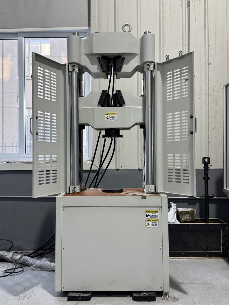
| Tensile Testing | Universal testing machines | Strength and elongation |
| Hardness Testing | Rockwell, Brinell testers | Consistent material hardness |
| Impact Testing | Charpy testers | Toughness for critical applications |
| Pressure Testing | Hydrostatic systems | Integrity of pressure components |
Process Control
Beyond testing, we maintain strict control over every variable—from wax injection parameters to shell building conditions. Consequently, this ensures consistency across all production runs.
Final Inspection
Depending on requirements, we employ multiple inspection methods:
CMM dimensional inspection for precise measurements
Non-destructive testing (X-ray, ultrasonic, dye penetrant) for internal integrity
100% inspection of critical features when specified
The Integrated Result
This integrated approach guarantees that every component—from one gram to one hundred kilograms—meets the highest quality standards.